Calculator Per FM DS 1-42 §2.3.1.2
Read SB from the chart that matches the exposing fire and the exposed-wall category. Choose the exposed-wall / exposure type to jump to the right source.
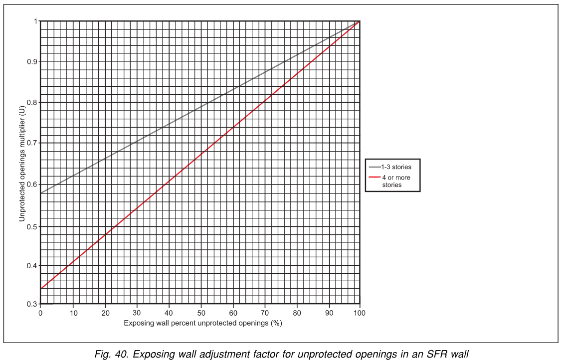
For an SFR (stable fire-resistive) exposing wall, read U from Figure 40 using the percent unprotected openings and number of stories. For a Non-SFR wall, U = 1.0. For an SFR wall and SFR roof, U = the actual unprotected-opening fraction (do not use Figure 40). See §2.3.3.
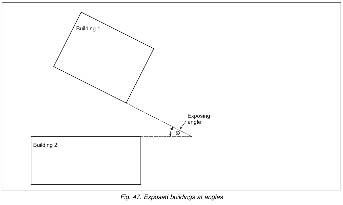
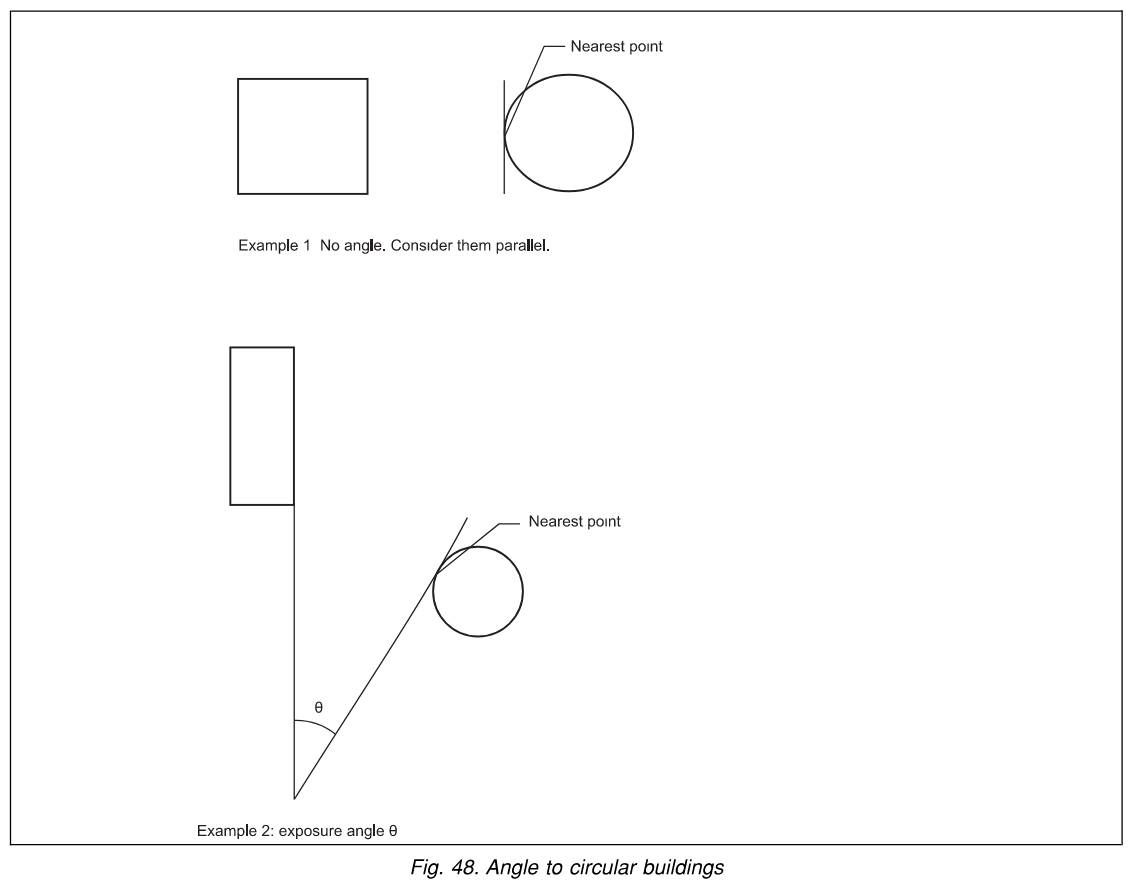
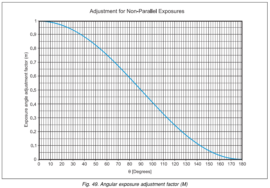
When the buildings are parallel, M = 1.0. When they are at an angle, determine the exposure angle θ (see Figures 47–48) and read M from Figure 49. See §2.3.6.
SB — Base separation distance Figures 37–39 & Table 3
The information needed to use Figures 37 through 39 is the exposed-wall category (§2.3.2), the classification of exposing-wall construction (§2.3.3), the exposing fire hazard category (§2.3.4), and the exposing-wall length L (§2.3.5, maximum 500 ft / 150 m). Use Table 3 instead for fire-rated exposed walls.
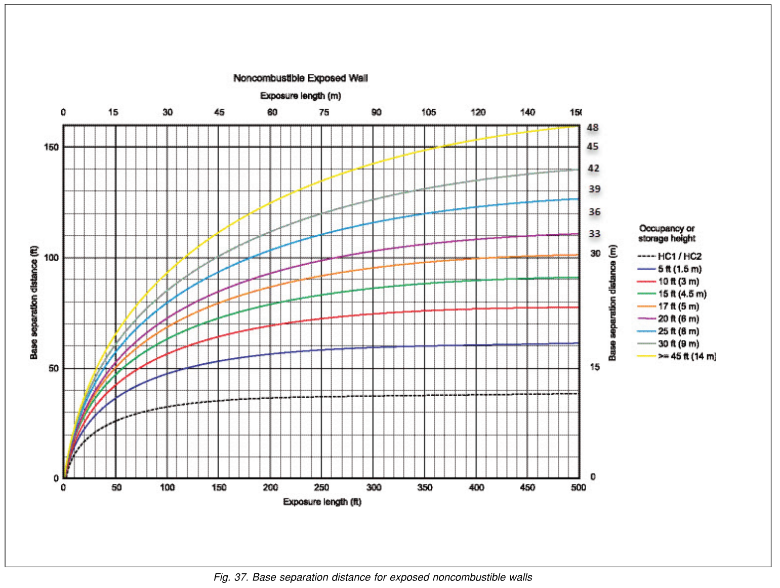
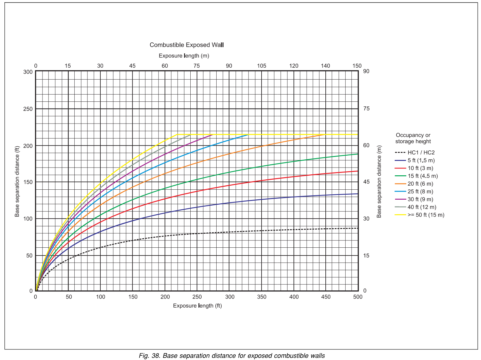
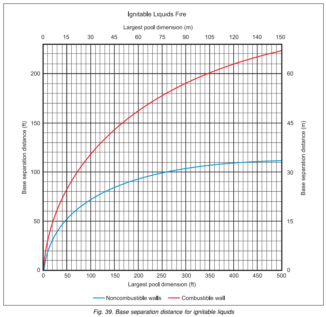
Table 3 — Base separation distance for fire-rated exposed walls
| Fire rating (hours) | HC-1 / HC-2 / HC-3 | Storage occupancy | Ignitable liquids | ||
|---|---|---|---|---|---|
| <30 ft (<9 m) | 30–45 ft (9–14 m) | ≥45 ft (≥14 m) | |||
| <1 | Categorize the exposed wall as either combustible or noncombustible (use Figure 37 or 38). | ||||
| 1 | 15 ft(4.5 m) | 40 ft(12 m) | 50 ft(15 m) | 60 ft(18 m) | 40 ft(12 m) |
| 2 | 10 ft(3 m) | 30 ft(9 m) | 40 ft(12 m) | 50 ft(15 m) | 25 ft(8 m) |
| 3 | 5 ft (1.5 m) | ||||
| ≥4 | None — only structural separation and minimum clearance for thermal expansion are required. | ||||
U — Unprotected opening adjustment factor Figure 40
For an SFR exposing wall, determine the total unprotected openings as a percentage of total wall area, then read U from Figure 40 for the corresponding number of stories (1–3 or 4+). For Non-SFR walls, U = 1.0. See §2.3.3.1–2.3.3.2.
M — Exposure angle adjustment factor Figures 47–49
When the exposed buildings are at an angle to one another, determine the exposure angle θ using Figures 47–48, then read the adjustment factor M from Figure 49. See §2.3.6.
How to use & methodology
- Pick units (U.S. or metric) at the top of the calculator.
- Step 1 — SB: Select the exposed-wall / exposure type, read the base separation distance from the matching figure (37/38/39) or Table 3, and enter it.
- Step 2 — U: Read the unprotected-opening factor from Figure 40 (SFR walls), or use 1.0 for Non-SFR walls.
- Step 3 — M: Read the exposure-angle factor from Figure 49, or use 1.0 for parallel exposures.
- The tool returns
SM = SB × U × M, then applies the §2.3.1.1 minimum-distance rules.
Minimum distances (§2.3.1.1)
- The minimum space separation is 10 ft (3.0 m) for any situation except exposed walls with a fire rating ≥ 3 hours.
- Maintain at least 125 ft (38 m) from any occupancy presenting an explosion hazard, BLEVE, PV rupture, or run-away reaction.
Scope & references
Background on the maximum foreseeable loss (MFL) concept is in FM DS 1-22, Maximum Foreseeable Loss. The space-separation methodology, figures, and Table 3 reproduced here are from FM DS 1-42, MFL Limiting Factors, Section 2.3. This tool covers the base calculation; it does not handle exposure-length adjustment for offset/overlapping buildings (Figures 42–46, §2.3.5.2), side-wall separation (§2.3.8), or the loading-station, rail, and vehicle-parking scenarios (§2.3.10–2.3.12) — consult the data sheet directly for those.
Engineering aid only. This calculator is a convenience interface to the FM DS 1-42 (Section 2.3) space-separation method. It does not replace the source document and is not a substitute for independent review by a qualified fire protection engineer. The user is responsible for correctly determining each factor (SB, U, M) from the governing figures and tables, for confirming the exposed-wall and exposing-fire classifications, and for evaluating all applicable scenarios and exceptions.